

Introduction
History of CAVE and BIM CAVE
Research Objective
Materials and Methods
Updating Process
Feasibility Test 1
Feasibility Test 2
Results and Discussions
Results of Feasibility Test 1
Results of Feasibility Test 2
Conclusion
Introduction
The scope of construction projects must be clearly defined before the beginning of the project especially since the owner, designers, and contractors need to determine clear designs before the construction has started to reduce construction costs and construction periods (Hendrickson, 2008). Thus, construction planning and designing are more significant than construction to proceed smoothly from the beginning of the construction to the end of the construction. Many efforts in the construction design field are being processed to increase the quality of plans and specifications (Arditi and Hansu, 1997; Tilley et al., 1999). However, change orders are ongoing issues in the construction industry due to dimension inconsistency in plans, and detail drawings insufficiency. Therefore, Building Information Model (BIM) is introduced to determine the designs that all the construction participants are satisfied (Eastman et al., 2011).
In the architecture field, BIM is actively employed to determine the construction design that all the construction participants are satisfied because the designs of the architecture projects are complicated compared to other types of construction projects (Azhar et al., 2008). Also, the number of construction participants is increasing because the architecture projects’ sizes are getting larger and more complicated (Hendrickson, 2008). Hence, the most critical key to a successful project is efficient communication and real-time information exchange among construction participants (Forcada et al., 2017). Thus, BIM and emerging technologies integrated design techniques are widely employed to determine flawless designs in the architecture field.
In the civil engineering field, infrastructures need specific design requirements or constraints for serviceability over a long life and obtaining better structural performance with spending less cost (Mei and Wang, 2021). Therefore, identifying optimal solutions is important for designers to strive based on advanced technologies such as BIM.
In the agricultural engineering field, there have been very few examples of introducing the innovated design methods for agricultural infrastructures such as open channels, pipe channels, aqueducts, etc (Kim, 2000; Kim et al., 2010; Kim et al., 2021). Even in the agricultural engineering field, it is not easy to look for examples of using BIM or other design tools. However, the importance of designing agricultural infrastructure is essentially the same as designing in other construction fields. The importance of design in the construction field and what kind of efforts are being made in each engineering field were explained, and the role of BIM was also introduced. In the construction industry, BIM is a well-known design visualization technology that contains relative information on each building component. The viewpoint of observation allows the user to understand the geometry of the layouts and the relationship of each structural member in a three-dimensional space (Eastman et al., 2011). A sense of presence is required to understand and transfer the experience and knowledge of the 3D space from a virtual environment to a real environment (Regenbrecht et al., 1998). Therefore, virtual environment technologies are integrated into BIM to get more perceptions and feel a sense of presence in the virtual environment. For employing the virtual environment using BIM, this study is based on the BIM CAVE (Building Information Model Computer-Aided Virtual Environment) application that was originally developed by Dr. Julian Kang at Texas A&M University. However, it only worked on Autodesk Navisworks 2012. Thus, after updating the existing BIM CAVE application to work on Autodesk Navisworks 2022, its feasibility is investigated to determine whether it is appropriate to review the agricultural infrastructure design.
History of CAVE and BIM CAVE
The CAVE (Cave Automatic Virtual Environment) system, first introduced in 1992 during SIGGRAPH, was designed to allow users to feel a sense of presence in a 3-dimensional computer model (Cruz-Neira et al., 1992). As BIM technology has been widely utilized in the construction industry, especially for informed decision-making during preconstruction coordination meetings, one may wonder if the CAVE system would enable them better to review the model (Regenbrecht et al., 1998).
At the University of Illinois, Chicago, the CAVE was developed by the Electronic Visualization Laboratory (EVL) in 1972 to create an immersive virtual environment through a demonstration of the relationship between the size of a screen and the sense of presence (Cruz-Neira et al., 1992). Since this CAVE system was not designed to handle BIM data, the concepts of the CAVE system are supplemented with BIM to provide a sense of presence for reviewing a displayed 3D model with the famous BIM commercial software (Nseir, 2011). The BIM CAVE application was updated to set up a top screen on the existing BIM CAVE system to review the relations of numerous MEP (Mechanical, Electrical, and Plumbing) components above the ceiling (Subramanian, 2012). The BIM CAVE was updated again to visualize the construction sequence instead of using the Gantt chart-style construction schedule. This updated application allows project participants to understand the construction schedule intuitively and navigate BIM to review each construction phase (Kuncham, 2013). Knowing that the original CAVE system was not designed to handle BIM data, Texas A&M University developed a BIM CAVE system in 2011 on top of a commercial BIM application so that one could review the model in the CAVE system without having to convert BIM file formats (Nseir, 2011). However, only three computers can be synchronized through the existing application, to create a virtual environment using BIM. In 2015, the existing BIM CAVE application was updated to synchronize nine computers to create a fully immersive virtual environment using BIM, as shown in Fig. 1 and Fig. 2 (Kang et al., 2015).
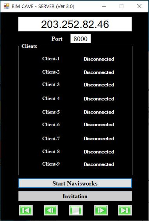
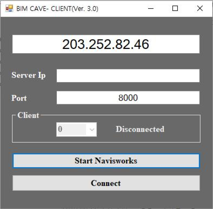
Fig. 2.
The building information model computer-aided virtual environment client application (Kang et al., 2015).
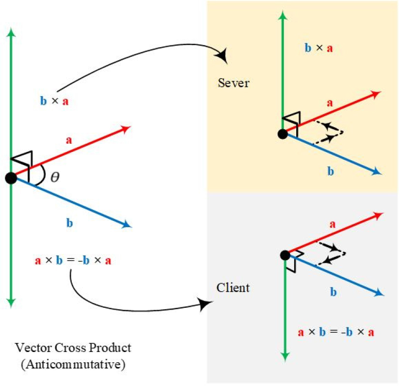
This BIM CAVE application was updated the BIM CAVE system should be synchronized between the server and the clients to produce the enclosed virtual display with the imported building information model. However, the client camera does not rotate to the left side and right side when the server camera is turned because the client follows the upside-down right-hand rule and the server follows the right-hand rule as shown in Fig. 3. In other words, the Up Vector is used to create a cross product in the rotation algorithm. Hence, the generated Up Vector of the new client becomes the offset with the generated Up Vector of the new server because the vector cross product is anticommutative.
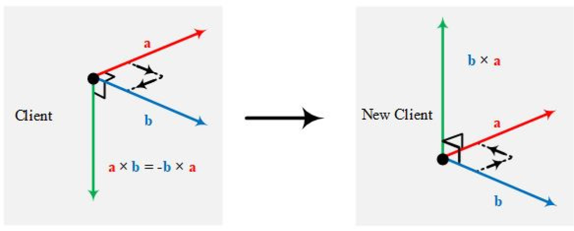
Thus, the View Direction Vector of the new Client is redefined to generate the Up Vector the same as the server for synchronizing between the client camera and the server camera as shown in Fig. 4.
The rotation of the redefined View Direction Vector and new Up Vector in the new client could be expressed mathematically using the following equation:
Server Cross Product:
Client Cross Product:
The View Direction Vector of the new client should be the same as the View Direction Vector of the new server to be synchronized as:
Research Objective
The existing BIM CAVE application still works based on Autodesk Navisworks 2012. The major issue with working on Autodesk Navisworks 2012 was that Autodesk software company no longer releases Autodesk Navisworks 2012 because its newer version is getting introduced every year. Also, the Autodesk Navisworks 2012 provides fewer functions than its newer version. Thus, the existing BIM CAVE application should be updated once more to be applicable and compatible with the newer Autodesk Navisworks, also known as Autodesk Navisworks 2022. The feasibility of the updated BIM CAVE application was experimentally investigated to determine whether or not the updated BIM CAVE application is suitable for reviewing the design of the agricultural infrastructure. In order to assess feasibility, eight interviewees were invited to review the design of the agricultural infrastructure displayed in the updated BIM CAVE system, and their objective evaluations were provided in this study. Also, through an experiment, we want to test whether there is a difference between the user’s recognition ability when using multiple screens and one screen. For this purpose, thirty users participated in the experiment.
Materials and Methods
Qualitative research, especially, interviews are most widely employed to evaluate or collect data from people after they experienced the developed system (Jamshed, 2014). There is no lack of whether interviews are systematic, semi-systematic, or lightly systematic (Mason, 1994). Thus, interviewees provided their opinions on whether or not it is feasible as the design review platform for the agricultural infrastructure in this research after using the multi-monitor system running on the updated BIM CAVE application. Also, a simple 3D office model was employed to determine whether or not the multi-screen system can be improved users’ cognitions in the virtual environment. After participants navigated the hallway to count the number of sprinklers, two simple questions were asked to check their cognitions in the virtual environment.
Updating Process
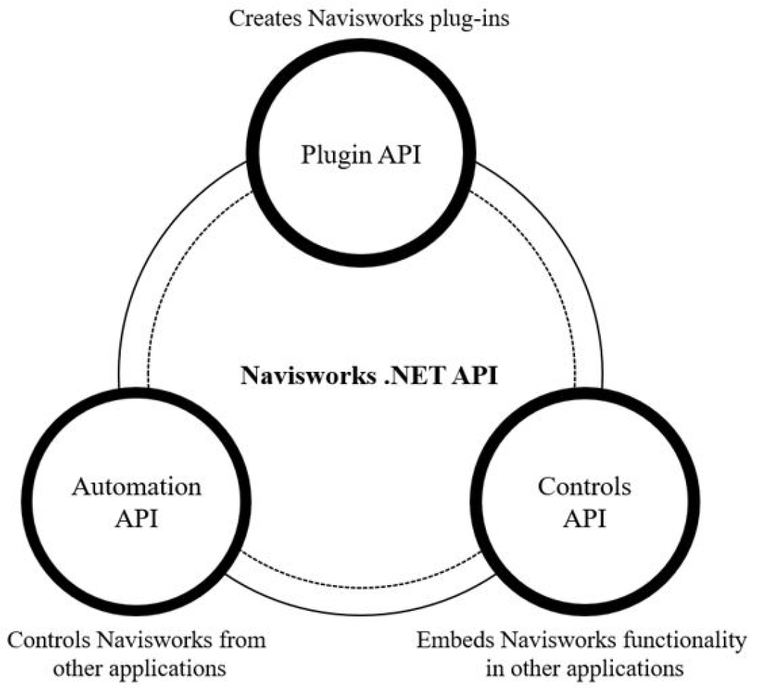
The BIM CAVE application was created based on Navisworks API (Application Programming Interface) in C# language (Kuncham, 2013). In other words, the application is based on the .Net Framework of the Navisworks API. This .Net Framework is a software framework that was designed to run on Microsoft Windows shown in Fig. 5. The .Net API consists of three components; Plugin API, Automation API, and Controls API. Here, the functionality in Navisworks can be extended through the Plugin API that is used inside the main window of the Navisworks application. Moreover, the Automation API works to control the Navisworks through other applications. Last, a custom-made application can be worked through the Controls API, although the Autodesk Navisworks software is not fully loaded (FIG Technologies Ltd, 2015).
Also, Autodesk Navisworks provides Navisworks Management Software Development Kit (SDK) for Navisworks developers (Autodesk Inc, 2022). Through the SDK website, all the references associated with Autodesk Navisworks 2022 were downloaded and inserted into the Autodesk Navisworks 2022 Plugins folders to activate the developed application for the user’s purposes. This SDK package runs the specific functions of Autodesk Navisworks 2022 that the user wants to use through the developed application, although it is commercial software. Through this process, the user can use more functions that the newer versions of Autodesk Navisworks provide as well as the resolution of pixels is increased. Compared to Autodesk Navisworks 2012, Autodesk Navisworks 2022 provides IFC performance improvement, file reader improvement, and newer functions such as BIM 360, Recap 360 (Chaisson, 2021). In order to make it compatible with Autodesk Navisworks 2022 instead of Autodesk Navisworks 2012, the older version of the .Net Framework should be replaced by the newer version of the .Net Framework. Since Autodesk Navisworks 2012 was based on .Net Framework 3.5, it should be upgraded to .Net Framework 4.8 and the target platform should be updated to x64 before the solution is built.
Feasibility Test 1
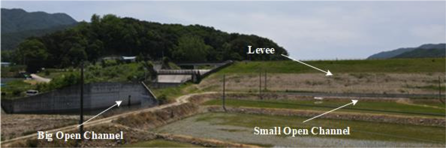
To review the design of the agricultural infrastructure, the Heungeop reservoir was selected, Heungop-myeon, City of Wonju, Gandwon Province. The agricultural infrastructure at Heungop reservoir mainly consists of one big open channel, multiple small channels, and one earth-filled levee shown in Fig. 6.
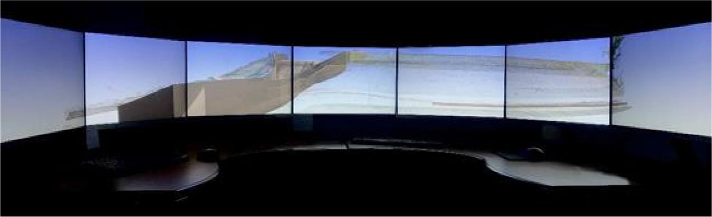
To move this existential agricultural infrastructure into the virtual environment running on the BIM CAVE application, multiple photos were taken using a high-definition camera attached drone to create a 3D model of all the agricultural infrastructure components except for a big open channel using photogrammetry. The Autodesk Revit produced a big open channel and a small open channel to merge with a 3D model created by photogrammetry. Through this procedure, a big open channel and a levee were produced in the virtual environment shown in Fig. 7. Eight interviewees participated in the test to investigate the feasibility of the multi-screen system using the BIM CAVE application as a design review system for a 3D model of the agricultural infrastructure. The eight participants consisted of 1 in their 30s, and 7 in their 20s from the educational institute. They navigated the 3D model using the multi-screen system running on the Autodesk Navisworks 2022 to review the agricultural infrastructure.
Feasibility Test 2
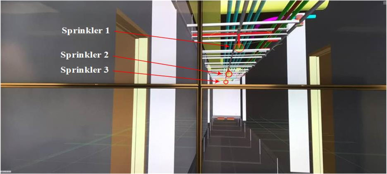
In addition, to check people’s cognition in the virtual environment, 23 sprinkler 3D models were created in a simple three-dimensional model of the office shown in Fig. 8. People counted the number of sprinklers when survey participants walk through the 3D model. They walked through the same 3D model two times using a single monitor and using multiple monitors to check whether or not the multi-monitor system is helpful to recognize the object in the virtual environment. This test was conducted by inviting 30 undergraduate and graduate students. All the test participants have a construction engineering background and the participants’ age is in their 20s to 30s. Hence, it can be simply assumed that they have experiences related to the virtual environment. Therefore, there is the appropriateness of the test participants.
Results and Discussions
Results of Feasibility Test 1
After eight interviewees had experience with this proposed system, their opinions are shown below.
∙ Interviewee 1: When comparing the head-mounted display with a multi-screen system, the multi-screen display system provides a wider viewing angle than the head-mounted display, which is similar to a human’s viewing angle. Also, the sense of presence was provided by a multi-screen system. The multi-screen system provided a field of view of 180°. Therefore, there was no difficulty in reviewing the 3D model of the construction projects such as the agricultural infrastructure when the field of view was up to 120°. However, it was difficult to review the 3D model when the field of view was over 120°.
∙ Interviewee 2: The multi-display clearly provided better visibility when I experienced multiple displays. I was first surprised at the existence of such a virtual environment, and I was surprised that all the structures related to the agricultural infrastructure reproduced in a virtual environment were similar to the real one and it was more detailed than my expectation. Since I had to recognize the 3D model in the multi-screen system, there was a bit of eye strain. The navigation in the virtual environment was not yet like a person was walking in the real world.
∙ Interviewee 3: When I experienced multiple displays, clearly, the multi-display provided better visibility. It was my first experience with this system, so it was difficult to operate when I navigated the 3D model of the agricultural infrastructure. When I was walking in the virtual environment using a mouse, it was difficult to recognize the shapes of the structure because the speed of the navigation was faster than the speed of my walking in the real world.
∙ Interviewee 4: Obviously, the screens surrounded the user. It felt like being in there. There was a slight time gap between each monitor when the scene on the screen tried to synchronize.
∙ Interviewee 5: The system made me concentrate on the 3D model. If screens were above and below the existing multi-screen system, the field of view could be wider. So, it would have been possible to provide a more realistic sense of presence.
∙ Interviewee 6: I was delighted to look at many 3D models that I could not see through just one monitor when I used multiple displays. My viewpoint was unrealistic because I had to use a mouse to move forward.
∙ Interviewee 7: I used a mouse to navigate the 3D model. It was unrealistic. It would be helpful to feel a sense of presence if there was no slight time gap for each monitor. Also, it would be great if there was a top screen.
∙ Interviewee 8: The side displays helped be more visible and easier to recognize the space in the virtual environment. Seeing the 3D model with 7 screens was more realistic than seeing the 3D model with 1 screen.
To summarize the interview results, most of the participants had a common opinion that it was enough to give a sense of presence in the virtual environment. However, there was a common opinion that the realism was reduced because a mouse was used when navigating inside a 3D model.
Results of Feasibility Test 2
The following questions were asked to the 30 undergraduate and graduate students to identify the difference in the recognition ability depending on the number of displays.
1) How many sprinklers did you find when experimenting with a single display?
2) How many sprinklers did you find when experimenting with multiple displays?
The results are shown in Fig. 9.
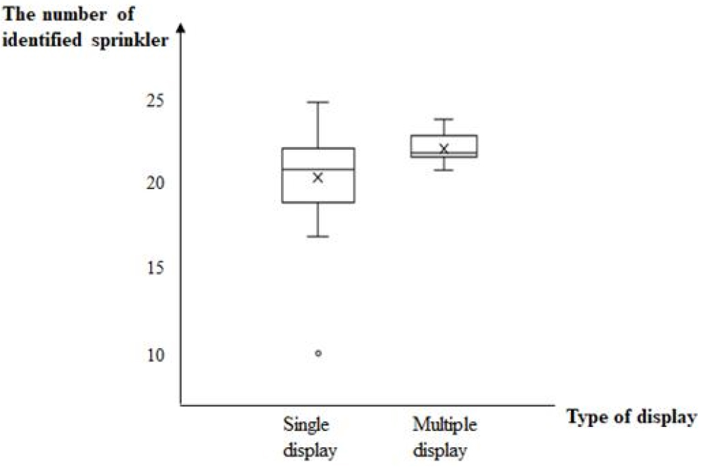
A t-test was used to test whether there is a difference in recognition ability depending on the number of display. The null hypothesis () and the alternative hypothesis () we used are as following equation:.
As shown in Table 1, the unequal variance t-test was performed because the variance difference between the two samples was significant. df in Table 1 stands for degree of freedom, SD in Table 1 means standard deviation for each group.
Table 1.
Results of the t-test
| Group | df | Mean | SD | t-statistics | p-value |
| Single | 29 | 20.53 | 2.79 | 3.14 | 0.003 |
| Multiple | 29 | 22.23 | 0.84 |
The Python library scipy was used for conducting the t-test, the code and results are shown in Fig. 10.
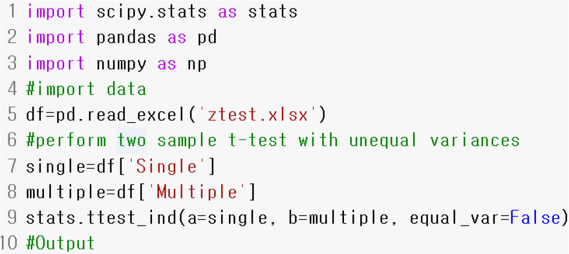
The p-value of the test is less than the significance level, we reject the null hypothesis. It means that multiple screens can significantly improve recognition ability compared to a single screen.
To sum up, the multi-screen system operated by the updated BIM CAVE application provides an enhanced sense of presence to review the design of the agricultural infrastructure. However, there are still limitations, such as walking in the virtual environment using a mouse and a slight time gap between each monitor when each computer tried to be synchronized for displaying a 3D model on multi-screen. Also, most of the population for interviews and simple surveys were students in their 20s. Therefore, in future studies, it is necessary that generations are expanded, and the number of the population is increased. In addition, the monitor size employed in this study was insufficient to provide the users with fully-immersion. However, this issue can be resolved through additional research grants in the future.
Conclusion
In this study, through interviews, the multi-screen display system running on the updated BIM CAVE application experimentally investigated whether it can be a design review system, including the agricultural infrastructure. The multi-screen system based on the updated BIM CAVE application was sufficient to provide a sense of presence to the user. Also, it had been determined that using multiple monitors rather than one monitor helps to review designs associated with the construction projects, including the agricultural infrastructure. However, it was determined that when walking inside the 3D model using a mouse, the reality decreased when the user navigated in the 3D model to review the design of the infrastructure. Also, there was a minor lag when each computer was synchronized to display a 3D model on a multi-screen system. It made that the user was not able to fully immerse in the 3D model when the user was reviewing the design. It is expected that if the drawbacks determined through the interviews and surveys were improved, it would be helpful in reviewing the design for agricultural and construction projects.
